Most quadcopters are powered by brushless motors. These have major advantages over brushed motors: less friction, less noise, and no brushes that need replacement. However, these advantages come at a cost — while brushed motors can be powered by a simple direct current, brushless motors require some sort of complicated, changing AC current. No idea how that works. Fortunately for us, we can just use an electronic speed controller. An ESC accepts a DC voltage, and takes care of running a brushless motor.
ESCs have a signal line to control their speed. It accepts a square wave running up to ~300hz. The speed is controlled with pulse-width modulation.
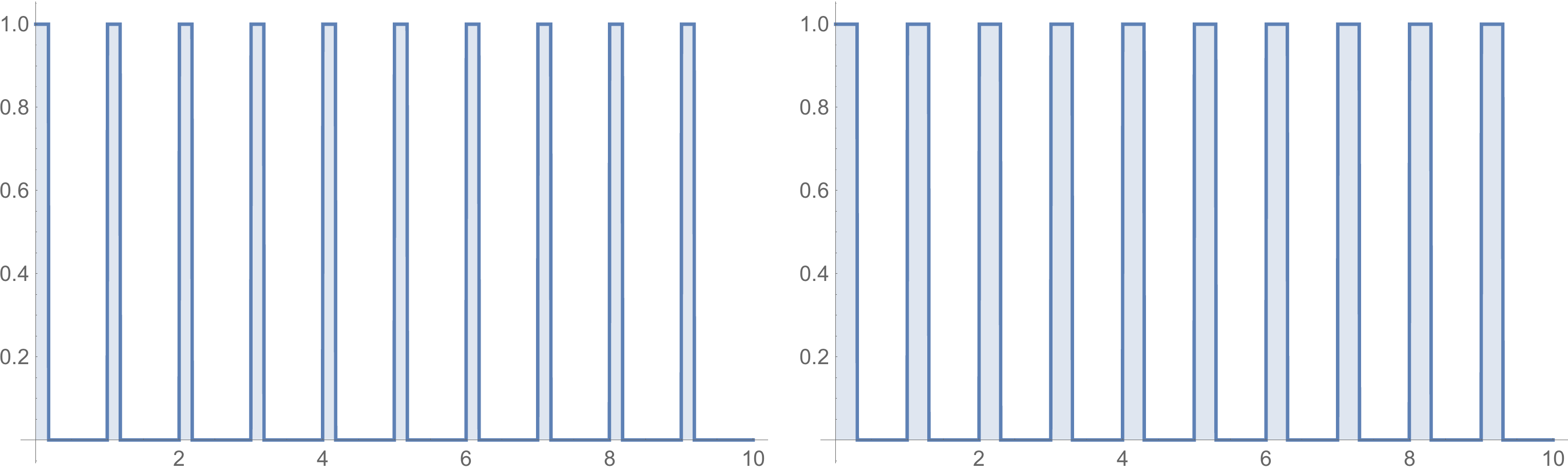
In the graph on the left, the power is on for 18% of the cycle, whereas the graph on the right has the power on for 30% of the cycle. This is how the speed is controlled — the frequency of cycles never changes, just the width of the powered pulses within each cycle. If the powered pulses are around ~1ms long, the motor will be off. At ~2ms, it'll be at max power. At ~1.5ms, it'll be at 50%.
Since this is a binary signal, we could theoretically generate this with our Raspberry Pi's GPIO pins. However, the timing of this pulse width needs to be incredibly accurate. Our program running on the Pi could freeze for a moment while the processor switches to the operating system, or depending on our programming language, it could get stuck garbage collecting for a split second. When being a millisecond off is the difference between no power and full power, we need something else than just the Pi to do timing.
I've seen guides online that use Arduinos attached to Pis to control motors. This probably works, but having to write and debug code for a second microcontroller seems like a lot of work. Instead, distantorion has a post on using a PCA9685 to generate the control signal, but their post is missing large chunks of code. Adafruit has another useful post on using the PCA9685, but for servo motors, not ESCs. I'm building autonomous drones with my friend Adam, and we merged these two sources together to write this article.
The Hardware
- A Raspberry Pi 2 — we compile Rust programs on the Pi, and it's way faster/easier with ARMv7 and a quad core processor.
- PCA9685 — Adam and I got one from Adafruit. Apparently these were originally for LEDs, since LED brightness is also controlled by pulse wave modulation.
- Electronic Speed Controller — we have a Hobbywing Skywalker, but apparently these somehow all have the same control interface, despite a lack of reasonable documentation online.
- Brushless Motor — we have a A2212 1000KV
I'm not going to explain how everything should hook up, but just connect voltages, grounds, SDAs, and SCLs, and you should be good to go. Also, remember that the ESCs should be powered separately from the Pi.
If you're wondering about SDA and SCL — they're part of a system called I2C, which lets you chain together a bunch of different devices to the same SDA (data) and SCL (clock) lines, and talk to all of them, one at a time, with a microcontroller. I haven't read the whole documentation, but roughly, every device has an device address and a number of byte registers. If you have the address of a device and the address of a register on that device, you can read and write that register's byte. Depending on the device, a register might be any number of things, like a mode flag, or a setting, or a read-only sensor reading.
The Code
We'll start out by simply importing the i2cdev crate (you'll need to add it to your Cargo.toml file), and useing some things we'll need later. We'll also add all the constants that I stole from the Adafruit code.
extern crate i2cdev;
use i2cdev::core::I2CDevice; // needed for trait functions
use i2cdev::linux::LinuxI2CDevice;
use std::thread;

// addresses
const MODE1: u8 = 0x00;
const MODE2: u8 = 0x01;
const LED0_ON_L: u8  = 0x06;
const LED0_ON_H : u8 = 0x07;
const LED0_OFF_L: u8 = 0x08;
const LED0_OFF_H: u8 = 0x09;

// Bits
const RESTART: u8 = 0x80;
const SLEEP: u8 = 0x10;
const ALLCALL: u8 = 0x01;
const OUTDRV: u8 = 0x04;

const TARGET_ADDR: u8 = 0x40;
We'll create a new I2C device, and wait a bit for a connection before sending it any messages.
fn main() {
    let mut device = LinuxI2CDevice::new("/dev/i2c-1", TARGET_ADDR).unwrap();
    thread::sleep_ms(100);
The PCA 9685 needs some modes to be set before it can be used. I took these values again, all from the Adafruit code.
    // reset PCA9685
    setPWM(&mut device, 0, 0, 0);
    device.smbus_write_byte_data(MODE2, OUTDRV);
    device.smbus_write_byte_data(MODE1, ALLCALL);
    thread::sleep_ms(5); // wait for oscillator

    // turn off sleep mode
    let mode1 = device.smbus_read_byte_data(MODE1).unwrap() & !SLEEP;
    device.smbus_write_byte_data(MODE1, mode1);
    thread::sleep_ms(5); // wait for oscillator
In this next chunk of code, we'll use setPWM. We'll define it later, but it accepts the I2C address of the PCA9685, a motor number (the PCA9685 can control up to 16 motors), and two values that tell it when in the cycle to turn on and off. These values are between 0 and 4096. You can change exactly how long a cycle of 4096 ticks takes by setting the 'prescale' value (see the Adafruit link for more info on that), but the default value of ~200hz should work fine for an ESC. A tick frequency of 200hz means each tick is 5ms. If we set the output to be powered for 1610 ticks, we'll get a (1610/4096)*5ms = ~2ms. Likewise, 810 ticks is (810/4096)*5ms = ~1ms. If you remember from way above, these are the approximate minimum and maximum values for controlling the speed of our ESC! In the code below, we'll start the power at tick 0, and stop it at either tick 810, tick 1610, or somewhere in between.
We still need to calibrate the ESC, so it knows the exact maximum and minimum widths of the pulse wave. Calibration works like this, according to distantorion:
- Unplug the ESC, remove any propellers that may be attached to your motor, and make sure the motor is attached to something. This is important so your motor doesn't fly up and cut you. distantorion describes this as a death machine that can cut flesh. Be careful.
- Send the max pulse wave of 2ms (1610 ticks) to the ESC.
- Plug in the ESC. It will beep thrice.
- Wait more than 2 seconds, but less than 5.
- Switch the pulse wave to the minimum, 1ms (810 ticks).
- Wait a bit, and the ESC will do a long beep. You're done!
ESCs remember their calibration, even when unplugged. If you start an ESC with a signal pulse wave around the minimum of 1ms, it will use the previous calibration settings, and skip all the steps above.
Anyways, let's actually write the calibration code.
    // UNPLUG THE ESCS AND REMOVE PROPS BEFORE RUNNING THIS

    // set max value and then wait for battery to be connected
    setPWM(&mut device, 0, 0, 1610);
    println!("Get ready to plug in the battery...");
    thread::sleep_ms(2000); // give the user 2 seconds to get ready

    println!("Now!");
    thread::sleep_ms(3000); // wait 3 seconds after beep to drop pulse length

    setPWM(&mut device, 0, 0, 800);
    thread::sleep_ms(5000); // wait 5 seconds and then try powering the motor

    setPWM(&mut device, 0, 0, 1200); // this is ~50% power
}
All that's left is the setPWM function. The PCA9685 has four I2C registers for each of its 16 motor outputs, which is a total of 64 motor control registers. They're one right after another, so Motor 2's registers are exactly 2*4 bytes after Motor 0's registers. Since both the on tick and the off tick go up to 4096, they're each represented by two byte-long registers. The code below does some bitwise manipulation to get the upper byte and the lower byte of each number before sending it off down the I2C bus to the PCA9685.
fn setPWM(dev: &mut LinuxI2CDevice, chan: u8, on: u16, off: u16) {
    dev.smbus_write_byte_data(LED0_ON_L+4*chan, (on & 0xFF) as u8);
    dev.smbus_write_byte_data(LED0_ON_H+4*chan, (on >> 8) as u8);
    dev.smbus_write_byte_data(LED0_OFF_L+4*chan, (off & 0xFF) as u8);
    dev.smbus_write_byte_data(LED0_OFF_H+4*chan, (off >> 8) as u8);
}
...or for a change of pace, perhaps you'd enjoy my other blog Agoraphobia →